4 Types of Regulating Motion in Blow Room Machinery
Introduction
This article is about types of regulating motion which is enhanced the productivity in blow room. The textile industry relies heavily on blow room machinery to process raw fibers at the beginning stages. As a primer to understanding the intricate workings of blow room machinery, we go in-depth into the detailed description of the action of regulating motion in blow room machinery. In the blow room, fibers are opened, cleaned, and blended before further processing, requiring a series of mechanical processes that work together to deliver the best possible outcome. In this article, we will described importance and types of regulating motion in blow room.
What is Regulating Motion?
As part of blow room machinery, regulating motion refers to the control and adjustment of various parameters to control material flow during fiber processing. This process involves monitoring and maintaining consistent feeding rates, controlling the speed of machines, and ensuring fiber distribution is uniform. In order to achieve optimal processing conditions and produce high-quality output, regulating motion is essential. A regulating motion maintains a steady flow of materials through blow room machinery by carefully controlling input parameters, such as fiber feeding rates.
Importance of Regulating Motion
- Regulating motion helps to control and adjusts the flow of fiber to ensure a consistent supply to the machine.
- By utilizing the regulating motion even and uniformed lap or card sliver is produced.
- Regulating motion helps to maintain optimal speed. so that efficiency of blow room machinery is increased.
- This motion ensure uniform feeding to next process.
- This motion minimizes downtime of machine and maximizes productivity of blow room.
- Regulating motion also helps to minimizes waste of blow room.
Types of Regulating Motion
There are many types of regulating motion. In modern blow rooms, the following regulating system is used to better regulate the material that is fed into the card frames in order to maintain a regular flow:
- By photo electric cell.
- By piano feed regulating system.
- By air pressure.
- By swing door.
1. By Photo Electric Cell
In this case, the light source and photo cell are situated opposite a window on each side of the machine so that light can pass through. If there is no material between the light source and the photocell when filling the cotton, the photocell is activated by the light and produces an electrical signal to stop the cotton feed until material flows through the photocell again. When cotton is present between the light source and photocell, the light is broken and the photocell produces a signal that continues the flow of materials. In this way, material flow is regulated.

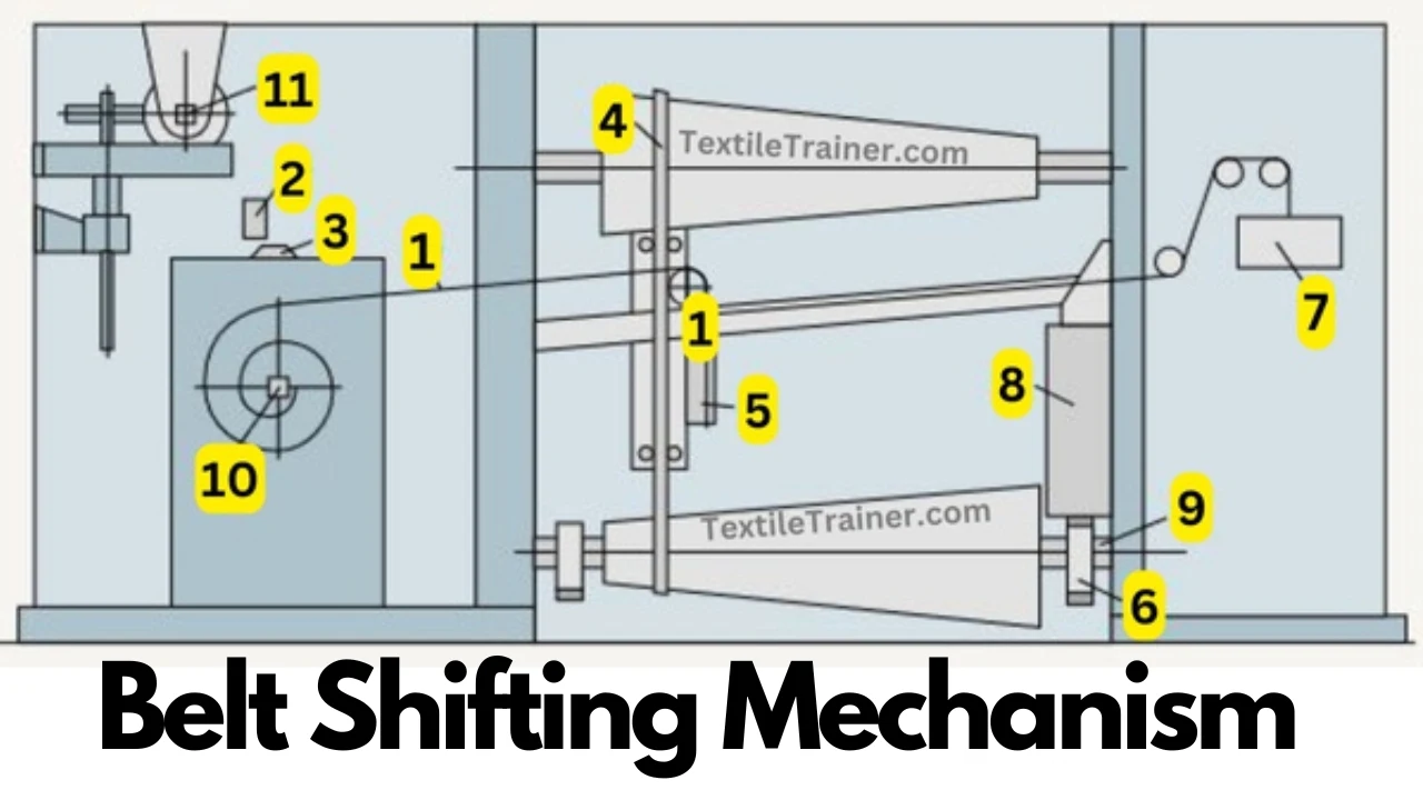
2. By Piano Feed Regulating System
Using the pedal movement caused by the thickness and thinness of cotton, the belt in the cone drums is moved by lever to adjust the feed roller speed to keep it constant. This system is used to layer/wave fiber uniformly to Schucher and create uniform laps. 16-18 pedal levers are mounted side-by-side the width of the machine and mounted on a knit edge rail to prevent friction.
The variation in the thickness of cotton at the feed point is multiplied five to six times at the tail end of the lever, which is usually in the form of a hook. On the hook end of each system, pedal links are provided. Three slots are used to link the pedal ends to tripod levers, which are connected to the pedals by simple levers up to the bottom long levers, and then it connects to the belt fork mechanism in the cone drum box.
3. By Air Pressure
Whenever air is introduced into the hoppers and cotton is being fed, air is locked by another portion. This air pressure is measured by a sensor, which is used to determine how much cotton is present in the hoppers. If the pressure is high, it stops feeding, and if the pressure is low, it allows more cotton to enter.
4. By Swing Door
In the swing door arrangement, the swing door is arranged in a way so that it is pushed down against the resistance of the counter balance spring once the hopper is about 2/3 to 3/4 full of cotton, and then the drive to feed the lattice is halted. The swing door is used to feed cotton uniformly to spiked lattice using a swing door.
Conclusion
A key component of the textile industry’s blow room process is regulating motion. It ensures uniform processing, ensures optimal machine speed and synchronization, and controls fiber flow. Textile manufacturers reap numerous benefits from the successful implementation of regulating motion techniques in the blow room.
References:
- Chowdhury, M. F. (2016). Manual of Short Staple Spinning. Dhaka: Granthanir Prokashoni.
- Corbman, D. P. (1983). Textiles Fiber to Fabric. NewYork: Mary McGarry.
- Hossain, M. S. (2014). Introduction to Textile Engineering. Dhka: Books Fair Publications.
- Kadolph, S. J. (2006). Textiles. New Delhi: Dorling Kindersley India Pvt. Ltd.
- Klein, W. (2016). The Rieter Manual of Spinng, Volume-II. Wintherthur: Rieter Machine Works Ltd.