Passage Diagram of Carding Machine is Described Easy Way
Introduction
This article discusses the passage diagram of a carding machine, as well as its working principle. A proverb says “Card is the heart of the spinning mill” and “Well card is half spun”. These proverbs illustrate the importance of carding in spinning. Carding is the process of reducing entangled fibers to filmy webs by working them between two closely spaced relatively moving surfaces closed with sharp points. The carding machine is located between the blow room and the drawing frame in the spinning process.Generally, carding use to create mixes of different fibers and colors.
By using carding machine, fiber become thinner evenly and distributed along a roll, facilitating spinning. There are two main ways to card fibers: by hand and by machine. The objective of this experiment is to learn about carded yarn by machine, or a passage diagram of a carding machine.
Objectives
- To remove the small trash and dust which have not been remove in blow room.
- Make the fibre parallel and straight.
- Elimination of the remaining impurities.
- To produce a thick untwisted rope of fibers called card sliver which is suitable for next processing.
Types of carding
Based on operating principle and construction carding machines can be of the following types:
- Stationary flat carding machine.
- Revolving flat carding machine.
- Duo or tandem cards.
1. Stationary flat carding:
In the stationary flat carding the flat does not rotate and the flat covers one fourth of the cylinder that is why it was named as stationary flat carding machine.
2. Revolving flat carding:
In the revolving flat carding machines the revolves or rotate along with the cylinder.
3. Duo or tandem cards:
As the name implies, tandem cards consists of two individual cards joined together to make up a unit, in which the doffer of the first card feeds fiber material to the taker-in of the second card.
Passage Diagram of Carding Machine
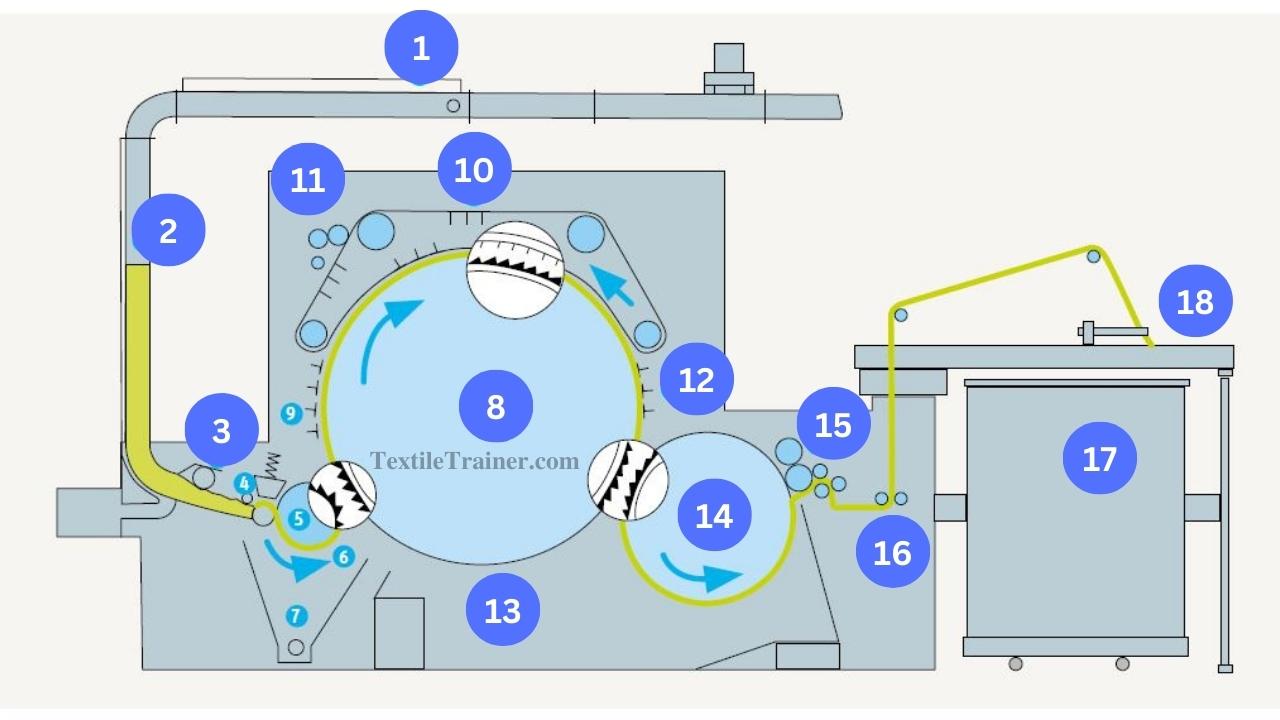
| 1= Pipe duct | 10= Flat |
| 2= Chute feed | 11= Cleaning unit |
| 3= Transport roller | 12= Fixed carding bars |
| 4= Feed arrangement | 13= Cylinder under case |
| 5= Taker-in | 14= Doffer |
| 6= Grid equipment | 15= Stripping device |
| 7= Suction ducts | 16= Calendar roller |
| 8= Main cylinder | 17= Sliver can |
| 9= Fixed carding bars | 18= Coiler |
A carding machine uses to process raw material after it exits the blow room. A pipe duct(1) supplies raw material into the feed chute(2) of the card. Approximately 500-900 ktex batts can make in the chute. Material is transported from this batt to the feed arrangement (4) by a transport rollor (3). It consists of a feed roller and feeder plate that pushes the fiber sheet slowly into the taker-in(5) while maintaining optimal clamping force. A taker-in passes flocks over a grid equipment(6) and transfers them to the main cylinder(8) from the portion of the sheet projecting from the feed roller.
The part of the sheet that project from the feed roller must be combed through and opened to flocks. By moving past mote knives, grids, carding segments, etc. Most of the impurities are lost in the process. The waste is carried away by suction ducts(7). In the actual carding process, flocks are carried along with the main cylinder, penetrate into the flats(10), and open up to individual fibers between these two devices.
A flat consists of 80-116 individual carding bars arranged in an endless pattern. A total of 30-46 flats are located in the carding position relative to the main cylinder; the rest are located on the return run. A cleaning unit(11) strips fibers, neps, and foreign matter during this return. The fixed carding bars (9) and (12) facilitate the operation of the card. The main cylinder’s underside is enclosed by grids or cover plates. The main cylinder carries along the loose, parallel fibers after the carding operation is completed. However, in this condition, the fibers cannot be transported as intermediate products. The doffer(14) is needed for this purpose as an additional cylinder.
The doffer is able to combine the fibers into a web because its peripheral speed is substantially lower than the main cylinder’s. Stripping devices(15) remove the web from doffers. After the rollers (16) have compressed the sliver to some extent, the coiler (18) deposits it in cans (18). Working rollers, cylinders, and floats are provided with clothing that wears out during fiber processing, and they must be reground on a regular basis.
Technical Data
| Raw materials | Cotton and man-made fibers up to 65 mm |
| Production | Up to 225 kg/h |
| Card sliver count | 4-20 ktex |
| Installed power | 23.5-29.8 kw |
| Delivery speed | Up to 330m/min |
| Cylinder speed | 600-900 rpm |
Conclusion
The heart of a spinning mill is the carding machine.Quality of yarn depend on carding machine. However, these the passage diagram of carding machine as well as the working principle of carding machine.
References
- Chowdhury, M. F. (2016). Manual of Short Staple Spinning . Dhaka: Granthanir Prokashoni.
- Klein, W. (2019). The Rieter Manual of Spinning. Switzerland: Rieter Machine Works Ltd.