Detailed Schematic Diagram of Yarn Winding Process
Introduction
In the preparation of yarn for various textile applications, yarn winding process is an important step. It involves transferring yarn from more extensive packages, such as cones or spools, to smaller, easier-to-manage forms, like balls or skeins. Before beginning the process, ensure the yarn is untangled and free of knots or snags. It can be done by hand using a yarn swift and ball winder or by mechanical winding machines in industrial settings, depending on the tools available.
The yarn is carefully wound around the swift, which holds the larger package, while the ball winder rotates to wind it onto a smaller package. Organizing the yarn this way prevents tangles and makes it easier to store, transport, and use in subsequent textile and craft projects. For larger-scale operations, mechanical winding machines are used. The machines can handle high volumes of yarn and produce tightly wound packages. The machines are often automated and can be programmed to meet specific winding requirements. This article will provide a schematic diagram of the yarn winding process.
Yarn winding Process
In the process of winding, there are three main regions that are involved.
- Region-1: Unwinding zone.
- Region-2: Tensioning and clearing zone.
- Region-3: Winding zone.
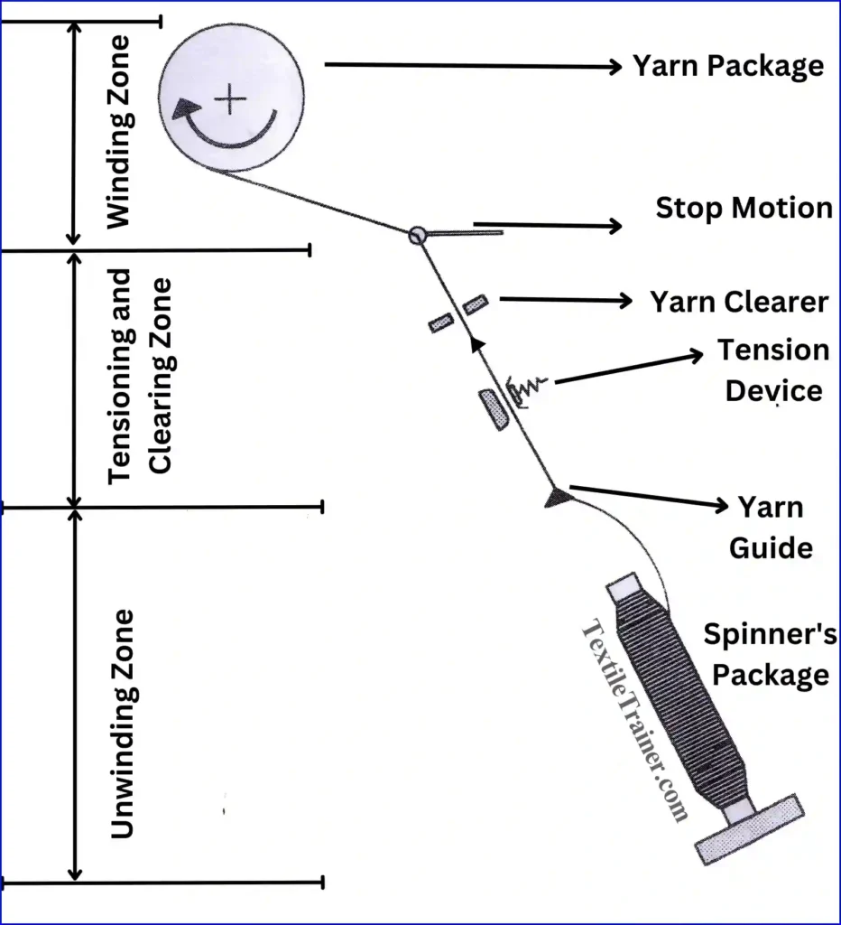
1. Region-1: Unwinding zone
This is the area in which yarn is released from the supply package before it is wound onto another package. Depending on the type, the supply package can be a cone or a bobbin. As part of the unwinding zone, yarn is fed in a controlled and consistent manner in order to ensure consistent and controlled yarn winding. During this process, the yarn package is held at an optimal position within the creel in order to facilitate easy unwinding once it has been placed there. In order to pull yarn from large packages, a couple of methods can be used, each of which has its own advantages. They are mentioned below:
- Side withdrawal unwinding
- Over-end withdrawal unwinding
Side withdrawal unwinding: the yarn does not rotate during side withdrawal since the spool is rotated during withdrawal. Thus, there is no change in yarn twist. As the yarn does not rotate, the spool must rotate in order to withdraw the yarn. Additional energy and equipment are needed for this, which is a disadvantage. When winding at high speeds, inertia can cause the spool to rotate, and this can affect yarn tension. Higher tensions can develop since the winder must overcome spool inertia upon startup.
Over-end withdrawal unwinding: With this system, the spool is not rotated in any way. As a result, it is possible to avoid the problems associated with rotating a spool. This is a simple method that does not require driving the spool in order to work. It has to be noted that the disadvantage of this system is the ballooning issue, which is caused by the way the yarn is withdrawn and unwound from the package at high speed. As a result of centrifugal force, the yarn follows a curved path, which results in the yarn ballooning out when it is rotated.
When the yarn is ballooned, the tension in the yarn will be uneven due to the uneven ballooning. It is important to note that when a complete wrap of yarn is removed from the supply package, the twist in that length changes by one turn each time. While this change may not be significant for regular round yarns if you are using flat yarns of metal, plastic, or rubber, even one twist is not permitted due to the fact that these yarns must remain flat. The over-end method of unwinding these yarns is impossible; therefore, the side withdrawal method must be used to unwind these yarns.
2. Region-2: The tensioning and clearing zone:
In this region, proper tension is applied to the yarn to ensure the package density and body can be achieved. There is an area known as the tensioning and clearing region, a specific area or mechanism in the winding process used to control the tension of the material being wound and clear any obstructions or entanglements. Three main components make up this region. They are:
- Tension device.
- Yarn clearers.
- Stop motion.
Tension device:
A tension device is used to maintain consistent tension in the yarn in order to achieve a uniform package density. This device also serves as a detector for excessively weak spots in the yarn that will break under the added tension induced by the tension device if those spots are excessively weak. Tension devices can be categorized into four main types in terms of function.
Capstan tensioner: It is commonly used in a variety of industries, including fiber, wire, and cable production, as well as paper processing, to control the tension with a cylindrical drum or pulley with a grooved surface. A capstan tension system generally guides material around it, such as fabric or wire. The grooves on the capstan’s surface provide friction, which helps maintain tension as the material passes through it. Adjusting the tension of a capstan can be done by adjusting its rotation speed or applying pressure to its surface.
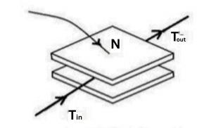
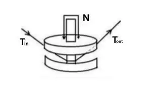
Additive tensioner: To change the tension, a dead weight or spring is used in conjunction with an application of a normal force (N) by means of a dead weight. There is a formula that can be used to calculate the output tension:
Tout= Tin+ 2µN
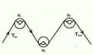
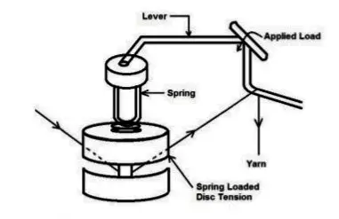
Combined tensioner: This is the most common type of tensioner, which consists of a tensioner that consists of at least a disc and a capstan. Normal force and wrap angle are two factors that change tension.
Tout= Tin(1+ eµα)+2µN
Automatic tensioner: In an automatic tensioner, tension is automatically adjusted and maintained throughout the winding process. Sensors, feedback mechanisms, and control algorithms monitor and regulate tension throughout the winding process. An automatic tensioner offers precise, real-time tension control, adaptive adjustments, and integration with the winding equipment in winding operations. A high-quality winding operation is ultimately achieved by improving productivity, ensuring consistent winding quality, and optimizing processes.
Yarn clearer:
An important function of a yarn detector is to eliminate places that are thin and thick from the yarn. There are two types of yarn detectors that are usually used:
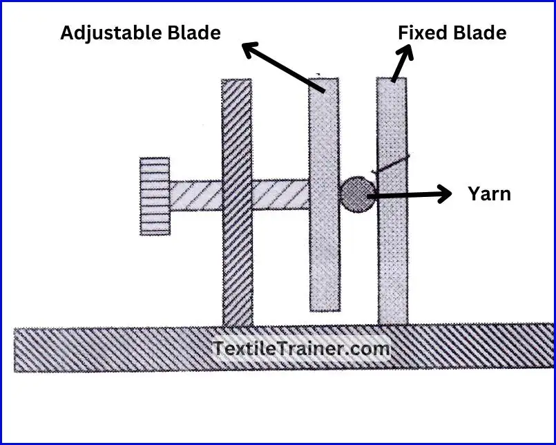
Mechanical: Mechanical clearers can be as simple as two parallel blades arranged in a straight line. A predetermined yarn diameter can pass through the plates when the distance between the plates is adjusted. Eventually, a thicker spot on the yarn will cause the tension on the yarn to build up and break. Consequently, this type of device can only detect thick yarns.
Electronic: Compared to the clearers of the past, today’s clearers have become far more sophisticated and contain electronics that constantly monitor the yarn in order to detect thin and thick areas. It is important to note that there are two main types of electronic detectors: capacitive and photoelectric.
In capacitive detectors, the mass of the yarn passing through the plates changes the capacitance. The system measures the mass of the yarn. The signal is not based on the yarn’s physical dimensions. A certain value in the signal causes the yarn to be cut when it reaches that value.
In a photo electronic detector, yarn passes between a light source and a photocell. Variations in yarn thickness cause fluctuations in light coming to the photocell, which changes the photocell’s resistance. A signal conditioning amplifier detects his resistance change and can send a signal to cut the yarn and stop the winding process.
Stop motion :
The purpose of a stop motion is to stop winding when the yarn breaks or runs out. Stop motions vary from machine to machine. Generally, a mechanical stop motion consists of a counter-weighted or spring-loaded sensing device held inactive if the yarn is present. Breakage or running out causes the absence of this restraining yarn and allows the sensing device to activate. Electronic stop motions sense the existence of the yarn without mechanical contact.
3. Region-3: The winding zone
It is in this region that the yarn package that will be suitable for further processing will be wound up. Depending on the next stage of processing, there can be a wide range of package configurations that can be obtained, including cones, tubes or cheeses, dye tubes or spools.
Conclusion
A uniform tension on the yarn is one of the basic requirements of winding. It is important to maintain uniform tension in the winding process and in the yarn in relation to the properties that are determined by tension. As long as the yarn speed is constant, then the tension in the package should be constant as well, so long as the tension on the yarn passing through the tension device is constant, i.e., the tension in the package is only a function of the yarn speed.
Reference
- Adanur, S. (2001). Handbook of weaving. Boca Raton: CRC press.
- Belal, P. D. (2016). Understanding Textiles for a Merchandiser. Dhaka: LB Graphics & Printing.
- V. Gordeev, P. V. (1982). Cotton Weaving. Russia: Mir Publishers Moscow.