Rieter Blow room Line Modern Flow Chart with Proper Picture
Introduction:
The blow room is the first step in the spinning process. Due to the air flow, this room is referred to as a blow room. The air flow in the blow room facilitates all processes. A blow room consists of different machines that are used to accomplish its objectives. Cotton tufts become smaller and smaller in the blow room.
Objectives:
- To know about blow room.
- To know flow chart of blow (Rieter)
- Function of different machine of blow room.
Rieter is the world’s leading supplier of systems for spinning yarn from staple fibers. With its headquarters in Winterthur (Switzerland), the company designs and manufactures machinery, systems, and components for the most efficient conversion of natural and man-made fibers into yarn. Through cutting-edge spinning technology, Rieter makes the textile value chain more sustainable by minimizing the use of resources. Over 225 years later, Rieter has 18 production locations across ten countries, with 5 590 employees globally, 16.4% of whom are in Switzerland.
Rieter Blow Room Line:
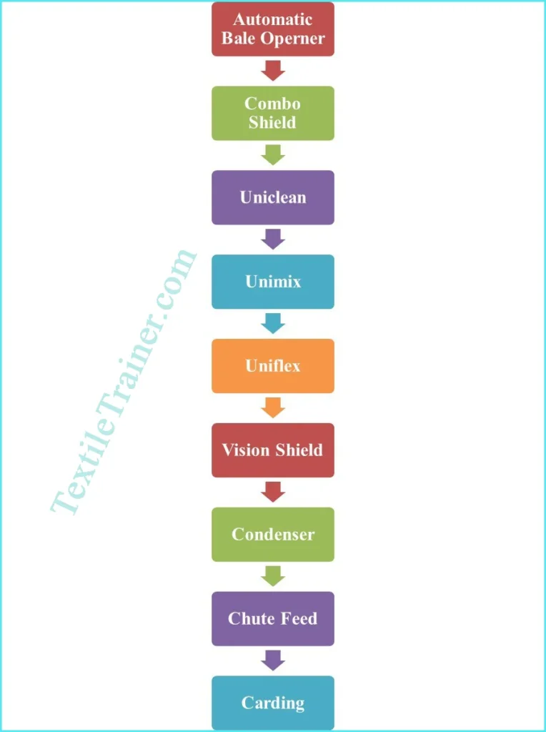
My goal is to briefly describe the flowchart of Rieter Blow room in this article.
Automatic Bale Opener
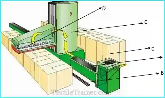
The feed duct(A) and two guide rails(B) are secured to the floor. The chassis(C), which moves back and forth on the guide rails and carries feeding head(D). Feeding head can moved up and down spiral deriver. Feeding head has individually replaceable double tooth discs and changes its direction of rotation on reversal of the direction of movement of the chassis, so that material can be extracted in both direction. The bales(E) are laid out to left and right of the machine and bales can processed from both sides simultaneously.
A microprocessor is provided for fully automatic extraction of material from the bales. A numerical keyboard can be used to manually enter the production rate and total weight of feed material. On the basis of the automatically detected bale heights, the machine then calculates all date required for fully automatic operation, including the penetration depth for extraction.
Technical data of automatic bale opener machine:
| Raw material | Cotton fiber and man-made fiber up to 65mm |
| Take-off unit(mm) | 2300 |
| Production (Kg/h) | Up to 2400 |
| Installed power (KW) | 14.7 |
| Machine body length (mm) | 2580 |
| Machine body width(mm) | 1230 |
| Machine body height(mm) | 2975 |
| Channel length(mm) | 10-50(in steps of 2.5m) |
| Net weight (kg) | 4050(without longitudinal parts, control |
Combo Shield:
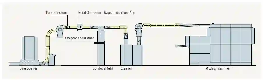
An elimination device, a metal extractor, and a spark detector are integrated into the transport duct. Spark detectors pivot the rapidly operating flap when they detect sparks or burning materials. Ideally, the receiving container should be outside the room where the material is received. In parallel with this, an alarm is given and the blow-room and filter installations are both turned off. Pivoting flaps remain in elimination until the line is switched back on. The device also detect matallic materials.
In the event that a foreign object is detected, the same rapidly operating flap is pivoted, which ejects the object into a container. It takes a certain amount of time for the flap to return to its original position after an adjustable time. Blower room lines remain on even though sparks are detected.
Uniclean:
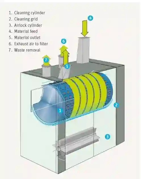
It is a coarse cleaning machine. The small tufts of uni-flock machine fie in this machine. There are opening roller consists with many spikes helps to opening the tuft of fiber and with combination of grid bar fiber is cleaned here. Trash , dust and foreign materials of cotton fiber are separated by this machine. cleaning is performed without nipping and is there for very gentle to the fibers and at the same time efficient. This ensures a high level of raw materials utilization. Up to 1200 kg/h can be produced by the machine.
Unimix
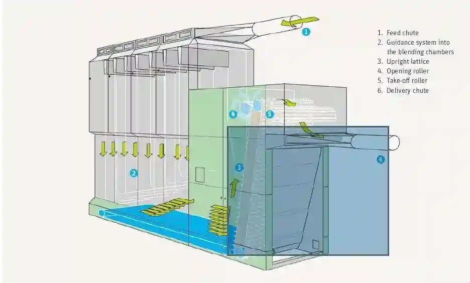
This machine consists of 6-8 chambers into which uniclean’s output material is blown. The machine is composed of three sections: the storage section, the intermediate chamber, and the delivery section. The tufts are fed pneumatically and simultaneously into eight chutes arranged one behind the other in the storage section. Conveyor belts feed the stock into the spiked lattice from the intermediate chamber.
As a result, the horizontal material columns divert from the vertical ones. Additionally to a condensing effect, the 900 deflection in the material flow also affects the timing and spatial distribution of the fiber packages. The special construction has a deflection of 900, and the individual chutes are separated from the lattice by different distances, which results in good long-term blending. An inclined spiked lattice and an evener roller open the material from the intermediate chamber, similar to a blending opener. Optical sensors ensure that only limited quantities of fiber stock are stored in the mixing chamber. The spiked lattice is taken off by a roller, and the next machine is fed by pneumatic suction.
Uniflex:
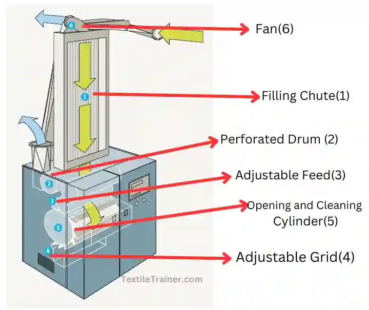
The tufts are drawn by suction from the preceding machine and ejected into a filling chute(1) by a fan (6). In the rear wall of the chute, individual aluminum lamellae with slot openings allow air to escape. Thus, both a lengthwise and a crosswise homogeneous batting laydown is formed. As a result of the adjustable chute depth, the lap weight required can be determined based on the production and type of fiber. Further transportation of the material is carried by a perforated drum(2) and a plain drum(3).
When starting up the fine cleaner, no manual intervention is necessary because the machine has automatic lap intake. According to the material being processed, the distance between feed trough(3) and opening cylinder(5) is adjusted by programming. The feed roll feeds the opening cylinder with material. Opening cylinders, available in different versions depending on the material requirements, take over the material. Vario set allows spinners to set rotation speed of opening cylinder depending on their objectives and raw materials. It has a grid (4) made of carding segments and knives that forms a cleaning surface and removes impurities.
The carding segments on the knives increase the degree of opening and therefore the degree of cleaning. Once again, the operator can adjust the knives on the grid according to his objectives and raw materials using the varioset.
Vision Shield:
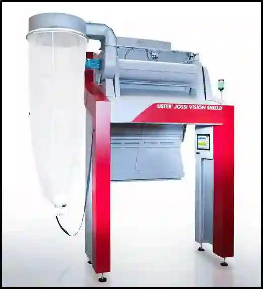
Producing contamination free yarn is one of the key quality objectives. Vision shields are used to create contamination-free yarn. In today’s textile market, there is a high level of competition. Every buyer wants products that are unique, of high quality, and free of contamination. Vision shield is used in blow room line to meet buyer requirements. With advanced technology, cotton fibers are cleaned with little loss of value.
Condenser:
The condenser is used to store heat in the blow room. This is one of the most important parts of the blow room. The main job of a condenser is to take fibers from one machine and supply them to another. The condenser ensures that the machine is fed regularly. There are three parts to this machine: a fan, a perforated roller, and a stripping roller.
Chute Feed:
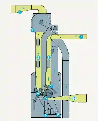
| 1= Material supply from blow- room 2= condenser 3= filling trunk with regulating flap. 4= Ridged rollers and feed roller with pedal lever. 5= kirscher beater 6= Hydraulic gear with servomotor. 7= Feed back from closed loop duct 8= Excess material 9= return feed rollers.10= Materials delivery to fan into circular duct. 11= beater motor |
Card feed material must be homogeneous, uniform from card to card, and remain constant over time. Many modern installations with pneumatic tuft feed systems have difficulty satisfying this requirement. Usually, solving the problem requires some level of design effort. In this case, lap feed was less problematic, since each scutcher lap was checked for constant lap weight and therefore indirectly for even laps. Moreover, the scutcher offers two more advantages: it is universally applicable and allows operation with a variety of blends. Compared with tuft feed systems, it is considerably less economical. It is therefore briefly discussed in this section, while the card feed system will be discussed in the next one.
Conclusion:
These are the Rieter Blow room. There are no all machine in our spinning lab. We saw only animation of all the that performed in blow room line specially Rieter Blow room. We can learn mechanism of all blow room’s machinery. This will help in our future life. Thanks to our teacher to helping us.
References
- Belal, P. D. (2009). Understanding Textiles for a Merchandiser . Dhaka: L.B graphics and Printing.
- Chowdhury, M. F. (2016). Manual of Short Staple Spinning . Dhaka: Granthanir Prokashoni.
- Kadolph, S. J. (2009). Textiles. New Delhi: Dorling Kindersley.
- Klein, W. (2019). The Rieter Manual of Spinning. Switzerland: Rieter Machine Works Ltd.