Drafting Arrangement System of Drawing Machine
Introduction:
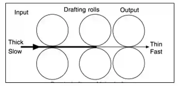
A draw frame is a machine where the slivers are doubled or combined, blended and mixed, leveled and attenuated transiently through a series of pairs of rollers arranged in a line. It is important to note that each pair of rollers moves faster than the previous one in the drafting arrangement. It is essential to know that the main purpose of implementing draw frames in the spinning procedure is to improve the yarn quality, particularly yarn evenness, by increasing the quality of the sliver.
The breaker draws frame and finisher draw frame are two of the most commonly used draw frames when dealing out the doubling and drafting of the card slivers during the process of dealing out the doubling and drafting. As part of the combing process, these draw frames are designated as either pre-comb draw frames or post-comb draw frames, according to the process stage. The drawing sliver’s quality is influenced by the drafting rollers’ arrangement and setting. The purpose of this experiment is to teach us about different drafting arrangements of drawing machines and the settings of those machines.
Objectives:
- Come to learn about drafting system of draw frame.
- Roller setting of drafting arrangement.
- Impact of drafting and doubling.
Elements of Drafting Arrangement System:
- Bottom roller.
- Top roller.
- Top roller pressure.
Now, let’s know all drafting arrangement system one by one.
1. Bottom Roller:
It is important to note that the bottom rollers of the device are made of steel and are mounted in the frame by means of needle, roller, or ball bearings. There is a positive drive from the main gear transmission that drives them. To improve their ability to carry the fibers along, they are formed with flutes of one of the following types:
a. Axial flutes.
b. Spiral flutes.
c. Knurled flutes.

2. Top Roller:
On the top of the rollers, there are no positively driven rollers. The rollers on the bottom contact the rollers’ surfaces to drive them. Applied to the top rollers of the machine is a synthetic rubber coating. It is essential to adjust the rubber’s hardness carefully. It is the degree of hardness that is specified by the degree shore.
| Soft | 60-700 shore |
| Medium | 70-900 shore |
| Hard | Above 900 shore |
3. Top Roller Pressure:
To clamp the fibers, the top rollers must be forced out at high pressure towards the bottom rollers. This pressure can be generated by:
- Dead weight (Now obsolete)
- Spring loaded (The most usual form)
- Hydraulic system (Rarely used)
- Pneumatic system (Rieter)
- Magnetic (Saco Lowell)
Types of drafting arrangement system :
Early draw frames had almost exclusively 4 over 4 roller drafting systems. The 3 over 3-4 roller system was developed out of this earlier version, and there after a multitude of new forms emerged. The drafting system may be described below:
- Conventional 4-o-4 roller drafting system.
- 3-0-4 roller drafting system.
- 3-0-3 roller drafting system with pressure bars.
- 4-0-3 roller drafting system with pressure bars.
- 5-0-4 roller drafting system
1. Conventional 4-O-4 Roller Drafting System
It is the old model drafting system. Here 4 top rollers are set on each one of the 4 bottom rollers. It can be used for all fibre lengths. But the setting can be changed by moving the 2nd and 4th roller slightly.
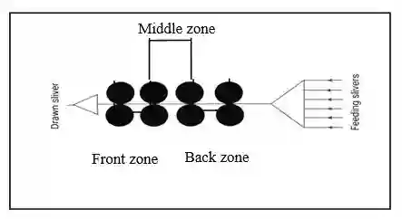
2. 3-O-4 Roller Drafting System:
The characteristic feature of this arrangement is engagement of the middle pressure roller with two bottom rollers. The two bottom rollers are carried in a common cradle and are not adjustable relative to each other. The basic concept can be improved by the inclusion of a pressure bar in the main drafting field. This type of arrangement is now found mainly in the combing room, but also still to some extent on draw frames for example in the Marzoli and vouk machine.
3. 3-O-3 Roller Drafting System with Pressure Bars:
Significantly the front rollers are affected by this. This is not simply a matter of stability; larger rollers can be operated at lower revolution speeds for a given circumferential speed. Increasing roller diameters, however, increases nip spacings at the same time. Therefore, a special guide system, known as the guide rail or pressure bar, is needed in the main drafting zone, at least for short fibers. In addition to operating from the bottom, it can also operate from the top. In addition to Rieter, Schubert & Salzer, and Toyoda, similar arrangements have been built or are being built.
4. 4-O-3 roller drafting system with pressure bars:
As a 4-over-3 roller drafting arrangement with pressure bars, this is also a 3-roller pressure bar arrangement, but a fourth roller also acts as a guide. Consequently, the web curves directly around the grooved roller into the delivery trumpet, allowing the sliver to form more easily. To keep the strain imposed on the top rollers low, they have a uniform diameter and are significant.
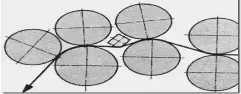
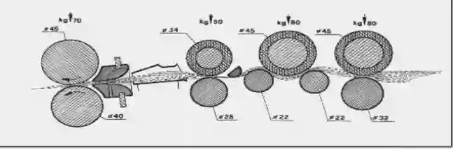
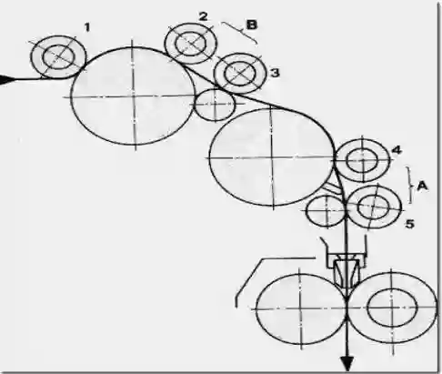
5. 5-O-4 roller drafting system:
Two large (90mm) and two small (28mm), non-adjustable bottom rollers support five pneumatically loaded pressure rollers in this arrangement. Two yokes suspend the pressure rollers. Although the three middle rollers can be replaced with rollers of 28 mm diameter, they have diameters of 39 mm. 5 over 4 roller drafting arrangement Drafting takes place in Field B (break draft) and Field A (main draft). It is possible to adjust the nip spacing by simply radial shifting rollers 2 and 4 according to the fiber length using a scale.
The main drafting field features a pressure bar to provide firm guidance, especially for shorter fibers. The drafting arrangement is aligned on a curve to guide the vertical and horizontal material flow. It is easy to service the system due to its curved disposition.
Effect of Drafting and Doubling on Sliver Quality:
Draft and doubling has significant effect on sliver quality which is described below.
Effect of Drafting:
- Drafting creates the parallelizing and straightening of the fibers in the sliver.
- Drafting creates heavy fiber to fiber and fiber to metal friction, thus eliminates considerable amount of dust from the material.
- Drafting action reduces the thickness and mass per unit length.
- Drafting may increases the irregularity.
Effect of Doubling:
- Doubling improves the short medium and long term evenness card sliver.
- Doubling provides blending/menins of the fibres of same or different materials. So sliver quality can be controlled by proper doubling.
- Doubling leads to between in regularity of drams sliver.
Conclusion:
During the drawing process, carded slivers are provided with parallel lines, hooks are removed, and the sliver is converted into a drawn sliver. This process involves passing a sliver between pairs of rollers so that it is elongated, doubled, and leveled. Draw frames are used for equalizing, parallelizing, blending, and dust removal. We learned different ways of setting up drawing frames based on the different drafting arrangement system we used in this experiment. Furthermore, we learned about the effect that doubling and drafting had on the quality of the slices. There will be many benefits in our future lives as a result of this.
You may read: