Material Passage Diagram of Lap Former Machine
Experiment Name:
Lab Report: Study on material passage diagram of lap former machine.
Introduction:
To produce superior quality cotton yarn, i.e., combed cotton yarn, we need to employ two more extra machines in our spinning line compared to our conventional carded yarn manufacturing process. As a first step, we must use lap formers to manufacture regular laps, followed by comber machines to make uniform slivers from those laps. A regular process flow chart of carded cotton yarn manufacturing shows that after being processed in carding, the carded slivers are fed into the breaker drawing frame machine.
In the breaker drawing frame, slivers are converted into more regular slivers and then sent to the finisher drawing frame for further quality improvement. The lap formers and combers are used, however, between those drawing frames in combed cotton manufacturing.
Objectives:
- To know about lap former machine.
- Come learn passage diagram of lap former machine.
- To know why lap former is import for good quality yarn.
- To know technical data of lap former machine.
Important of Lap Former Machine:
A yarn that is made up of a longer length of fiber tends to have fewer irregularities in subsequent processing. These yarns are also superior in quality and have a lower percentage of hairiness as well. We obtain such uniform and regular slivers from a comber machine as they are free of a predetermined length of short fibers. The use of a comber machine in our spinning line is therefore necessary for the manufacture of yarns of such higher quality. In order to manufacture these uniform slivers in comber, which ultimately lead us to create extraordinary yarn, we must also produce a number of uniform laps.
This is where lap formers come in handy. Due to the fact that the comber machine cannot process drawing frame slivers directly and relies on lap feeding only, the lap former machine was required. The lap feeding system also helps the comber comb it more efficiently than a hypothetical sliver feeding system. The lap former is responsible for developing the laps that feed the comber. A lap is achieved by combining or doubling a certain number of slivers from the breaker drawing passage, such as 16 to 32 slivers or even 64 slivers at times.
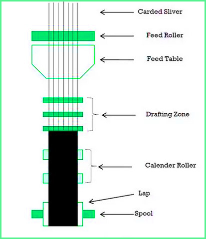
Diagram of Lap Former Machine:
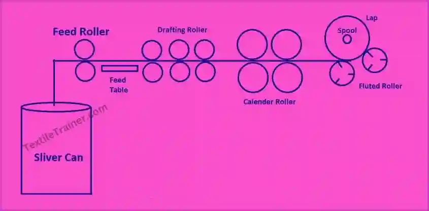
Working Principle of Lap Former Machine:
The lap former usually carries two creel rails with twenty eight cans of drawn sliver from the first draw frame. After passing the slivers through the guide plate at the rear, they are then passed over a distinctive spoon. They then pass through a V-shaped feed table that links them to the neck. After passing through the slivers, the fibers are finally sorted, straightened and parallelized due to the draft. The lap sheet is then compacted into a sheet by two pairs of calendar rollers. The Lap Stop Motion stops the machine immediately when the appropriate lap length has already been rolled to the spool and enormous pressure is applied to the bobbin to achieve a long compressed lap.
Technical Specification:
| Parameters | Rieter E 35 | Rieter E 32 |
| Production | Up to 520 kg/hr | Up to 350 kg/hr |
| Input Weight | Maximum 140 ktex | Maximum 140 ktex |
| Lap Hank | Up to 80 ktex | Up to 80 ktex |
| Lap Weight | Fixed 25 kg | Up to 25 kg |
| Lap Width | 300 mm | 300 mm |
| Delivery Speed | Up to 180 m/min | 70-140 m/min |
Dimension of Sliver Lap:
| GSM | 52-72 g/m |
| Width | 220-301 mm |
| Diameter | 505 mm |
| Weight up to | 26 kg |
Conclusion:
A yarn’s quality is primarily determined by its staple length and the uniformity of its length. In order to produce a yarn of greater quality, short fibers must be eliminated, which requires the use of a comber machine. Considering the comber machine relies on a lap feeding system while the previous machine produces drawn slivers, a lap former machine is necessary to produce lap. Through this experiment, we have gained knowledge of why lap former machines are important and how to use them. As well as learning technical specifications of lap former machine, we also performed an experiment with the help of our teacher.
You May Read:
- Dynamic Layout Plan of Spinning Lab.
- Bale Breaker Material Passage Diagram: Easy Description.
- Step Cleaner Machine: Simple Working Principle.
- Hopper Feeder Machine in Blow Room with Simple Working Principle.
- Porcupine Opener Machine in Blow Room: Simple Working Principle.
- Scutcher Machine in Blow Room: Feed to Carding Effective Way.
- Material Passage Diagram of Carding Machine with Easy Description.