Introduction:
The bobbin building mechanism in a speed frame is a critical component in the process of transforming sliver into yarn. The speed frame is an essential machine in the spinning mill, and its bobbin building mechanism contributes to the formation of uniform and well-wound bobbins. the bobbin building mechanism in a speed frame is a sophisticated process that involves drafting, twist insertion, controlled winding, traverse mechanisms, and tension control. The efficient operation of this mechanism is essential for producing high-quality yarn packages that meet the standards required for downstream processes in the textile industry.
Bobbin Building Mechanism:
During a winding operation ,bobbin building device must perform the following three tasks:
- Shifting the cone belt: As the diameter of the bobbin increases, shift the cone belt accordingly;
- Reversal of the bobbin rail movement: At the upper and lower ends of the lift stroke, reverse the direction of the bobbin rail;
- Shorting the lift: To form tapered ends on the bobbins, shorten the lift after each layer
In order to adapt the change gear positions to the prevailing conditions, it is necessary to adjust the moment for each change-over and the magnitude of the adjustment based on the roving hank and material. We will present a brief description of a builder motion for a roving frame in the following sections, where the majority of movement changes are performed electro pneumatically.
1. Shifting the Cone Belt:
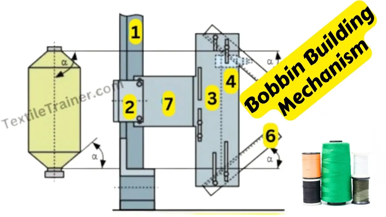
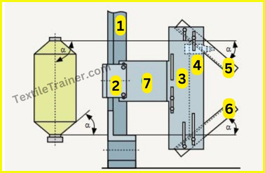
The machine unit that induces all changes is the changeover mechanism, which comprises metal brackets (3/7) and rods (5/6). This mechanism is attached to the bobbin rail (2) and is raised and lowered as a unit with the rail. A stationary pin is struck by one of the rods (5/6) on the up- ward stroke and by the other on the downward stroke, and each time a micro switch (4) emits a pulse. Each pulse from micro switch (4) actuates a release mechanism to permit rotation of the ratchet wheel through one half-tooth.
2. Reversal of the Bobbin Rail Movement:
3. Shorting the Lift:
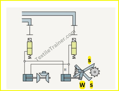
It is possible to adjust the inclination of rods 5 and 6 (figure-3) to correspond to the taper of the bobbin ends. During winding of a package, the ratchet is rotated at every change-over, and the micro switch (Figure-3) is gradually shifted further to the right on a slide as well. As a result, the rods engage the microswitch consistently earlier during the lift stroke, resulting in a continuous decrease in rail lift. Thus, the bobbins are tapered.
Conclusion:
As an integral part of the spinning process, the bobbin building mechanism represents a key link between raw materials and the production of quality yarn. Besides technological sophistication, the company is committed to delivering yarn packages that meet industry standards. Ultimately, bobbin building mechanisms play an integral role in ensuring textile manufacturing success and competitiveness.
You May Read:
- Dynamic Layout Plan of Spinning Lab.
- Bale Breaker Material Passage Diagram: Easy Description.
- Step Cleaner Machine: Simple Working Principle.
- Hopper Feeder Machine in Blow Room with Simple Working Principle.
- Porcupine Opener Machine in Blow Room: Simple Working Principle.
- Scutcher Machine in Blow Room: Feed to Carding Effective Way.
- Material Passage Diagram of Carding Machine with Easy Description.
- Material Passage Diagram of Lap Former Machine.
- Working Principle of Comber Machine: Better Quality Yarn.
- Working Principle of Speed Frame in Ring Spinning with Simple Description.
- Ring Spinning Frame: Working Principle is Describe Very Easy Way.
- Easy Way: Autoconer in spinning working Principle.
- Belt Shifting Mechanism of Speed Frame with Proper Simple Figure.
