Introduction:
Belt shifting mechanism of speed frame is described in this article. Fibers are converted into low twist yarn called roving using the Simplex intermediate process. It is not suitable for yarn manufacturing because the sliver taken from draw frame is thicker. The purpose of this process is to prepare an input package for the next step. This package will be prepared in a compact package known as a bobbin. Speed frames are complex, prone to fault, cause defects, increase production costs, and deliver the product to the customer. It is this winding operation that makes Seed frame complex. Speed frame also called below three name:
- Roving frame.
- Simplex frame.
- Flyer frame.
Why Speed Frame is Important?
Speed frames are used for two basic reasons.
- In terms of the first reason, the draft needed is in the region of 300-500. Sliver is a thick, untwisted strand that tends to create fly and is hairy. The drafting arrangements of ring spinning machines, in their current forms, are not capable of processing. It is significantly better suited to this purpose to use fine, twisted roving.
- Draw frame cans represent the worst possible way to transport and present feed material to the ring spinning frame.
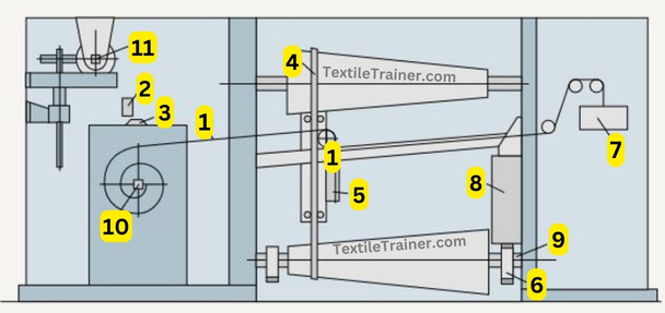
Diagram of Belt Shifting Mechanism:

Main Parts of Belt Shifting Mechanism:
| 1= Wire rope | 6= Pinion |
| 2= Belt guide | 7= Weight |
| 3=Roller | 8= Lifting chain |
| 4= Shaft | 9= Cylinder |
| 5= Belt guide | 10= Ratchet wheel |
Working Principle of Belt Shifting Mechanism:
As part of each change-over operation (after each stroke), the ratchet wheel (10) is permitted to rotate by half a tooth. Through a gear train consisting of change wheels and an eccentric, this ratchet steps out the wire rope (1) and therefore moves the belt guide (5) to the right. A weight (7) exerts tensile force on the belt to cause it to move. The belt must be shifted through corresponding steps depending on the roving hank. Bobbin diameter increases more or less rapidly depending on the roving hank. Changing the degree of shift, which depends on the thickness of the roving, is accomplished by replacing the ratchet wheel or (generally nowadays) by switching to change wheels. As a result of inserting a ratchet wheel with fewer teeth, the belt is shifted through larger steps, i.e. it progresses more quickly. After the bobbin is fully wound, the belt must be moved back to its starting point. Today, this is usually done by an auxiliary motor.
You May Read:
- Dynamic Layout Plan of Spinning Lab.
- Bale Breaker Material Passage Diagram: Easy Description.
- Step Cleaner Machine: Simple Working Principle.
- Hopper Feeder Machine in Blow Room with Simple Working Principle.
- Porcupine Opener Machine in Blow Room: Simple Working Principle.
- Scutcher Machine in Blow Room: Feed to Carding Effective Way.
- Material Passage Diagram of Carding Machine with Easy Description.
- Material Passage Diagram of Lap Former Machine.
- Working Principle of Comber Machine: Better Quality Yarn.
- Working Principle of Speed Frame in Ring Spinning with Simple Description.
- Ring Spinning Frame: Working Principle is Describe Very Easy Way.
- Easy Way: Autoconer in spinning working Principle.


2 thoughts on “Belt Shifting Mechanism of Speed Frame with Proper Simple Figure”