Material Passage Diagram of Carding Machine
Experiment Name:
Lab Report: Study on material passage diagram of carding machine in cotton spinning.
Introduction:
By using carding, locks sand unorganized clumps of fiber are broken up and then aligned so that they are parallel to each other. Carding also can be used to create blends of different fibers or different colors. It plays a crucial role in incorporating different functions that are essential to ensuring that a product’s quality is maintained.
Carding is generally done by inputting lap into the arming machine to obtain carded sliver. It is known as the “heart of the spinning mill.”
Objectives:
- To know about different parts of carding machine.
- Come to learn different mechanism of carding machine.
- To know the material flow path of carding machine.
- To define material contact roller rotating position.
Diagram of Carding Machine:
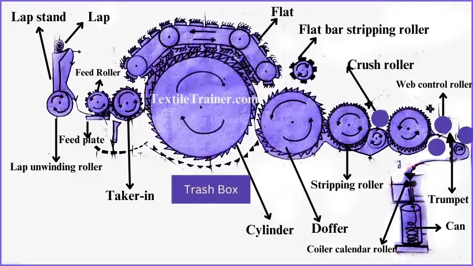
Main Parts of Carding Machine:
- Lap stand: It is a lap pin where wounded lap gets support.
- Lap Unwinding roller: It is used for unwinding lap from lap pin for further processing. Its diameter is inches.
- Feed Plate: Used for feeding fiber in the machine.
- Taker in: It has metallic clothing with spike used for feeding fibers in cylinder. Its diameter is 9 inches.
- Trash Box: This box contains the impurities which is removed from lap.
- Cylinder: Used for individualizing and cleaning of fibers. It consists of 106 flat bar and has a Dia of inches.
- Doffer: Help in stripping action. It has a Dia of 27 inches.
- Stripping Roller: Tears fiber, where neps formed it reduced. There are two stripping rollers, and their diameter are inches and 4 inches.
- Crushing Roller: It applies crushing on fibers. There are two crushing rollers. Each of them have diameter of 3.25 inches.
- Web Control Roller: It creates fiber sheet shape. In the machine. There is also two web control roller and each of them have diameter of 3.25 inches.
- Condenser/Trumpet: Sliver creating mechanism. In the machine, there is two type of calendrer roller.
- calendar roller: It applies calendaring on the sheet. Machine consists of two calendrer rollers. Each of them 3 inches of diameter.
- Coiler: It creates coil form of sliver.
- Coiler Calendar Roller: It indicates the direction of coiler. It sits on the coiling head. It has a diameter of 2.5 inches.
- Coiler plate: It located on the top of can. Can also joints with that.
- Can: It stores sliver. It also rotates with coiler plate.
Working Principle of Carding Machine:
- In a blow room, a lap stand is used to transfer blow room lap from the scutcher machine to the carding machine.
- The lap stand serves as a lap storage unit for the carding machine to work continuously. The unwinding roller unwinds the lap.
- Feeding table or feed plate procedure, ensuring proper tension and uniform feed to the lap. Lap unwinding roller moves the lap forward towards the feed plate.
- A feed roller is used to feed the lap into a taker-in or licker-in machine.
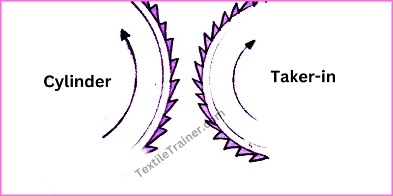
- The taker-in or licker-in is located after the feed roller and before the cylinder. The taker-in creates microtufts and removes seed fragments and a large amount of impurities.
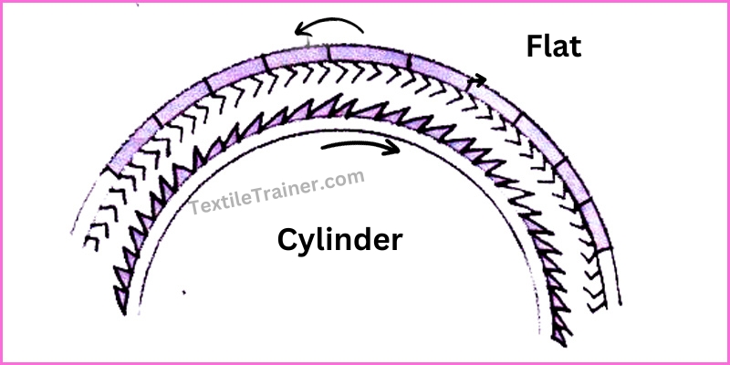
- There is a main carding action between flat bars and cylinder. The flat bar wire and the cylinder wire are in opposite directions. 40 flat bars are generally on the surface of the cylinder and act as carders.
- A flat bar cleaning brush roller or flat bar stripping roller cleans flat bars.
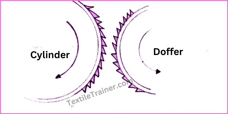
- A doffer collects fibers from the cylinder into a uniform fleece, which is delicately removed to form a card web because of its slow speed.
- The first stripping roller collects the fibers from the doffer and passes them to the crush rollers. At the top of the stripping roller, there is a brush that cleans the surface of the stripping roller of extra fibers.
- The crushed roller crushes trash particles into dust.
- Fiber web is controlled by a roller and gathered at a point by the roller.
- Sliver fibers are compressed and condensed in the condenser to gain sufficient strength.
- The sliver can is placed on the coiler table, both are rotating. This rotation causes the sliver to wind into the can.
Action in Carding Machine:
- Combining action: It occurs between the feed roller and taker in. Both surfaces have the same wind direction.
- Carding Action:-During this process, the wires on two surfaces are in the opposite directions and are inserted between the flat bar and the main cylinder.
- Stripping Action: –Here, the direction of wires of two surfaces is the same between the taker-in and the cylinder, doffer and stripping roller.
- Doffing Action: –This happens between cylinders and doffers. Fibers are transferred here between them.
Conclusion:
The carding machine is a machine that arranges fibers in parallel fusion. We also learn from this experiment which part of the carding machine is required for which mechanism. Therefore, we can say that from this experiment, we gained a comprehensive understanding of the carding machine and how it operates.
You May Read:
- Dynamic Layout Plan of Spinning Lab.
- Bale Breaker Material Passage Diagram: Easy Description.
- Step Cleaner Machine: Simple Working Principle.
- Hopper Feeder Machine in Blow Room with Simple Working Principle.
- Porcupine Opener Machine in Blow Room: Simple Working Principle.
- Scutcher Machine in Blow Room: Feed to Carding Effective Way.
- Study on Flow Chart of Trutzschler Blow Room for Cotton Spinning.
- Study on Modern Flow Chart of Rieter Blow room Line with Proper Picture.
- What is Spinning? Different Types of Yarn Spinning is Described in Easy Way.
- Working Principle of Rieter UNIFlex for Unparalleled Production in Blow Room.