Jute First Drawing Frame: Easy Material Passage Diagram
Experiment Name:
Lab Report: Study on material passage diagram of jute 1st drawing frame./ Study on working principle of jute first drawing frame.
Introduction:
The process of drawing is used to reduce the width and thickness of slivers by mixing 4 to 6 slivers together simultaneously. In most mills, there are three drawing passages used in Hessian and two drawing passages used in Sacking. Main objectives of drawing frame is straightening and parallelization of jute sliver. drawing frame also reduce the weight per unit length and reduce thick and thin place of the sliver. In this experiment, we will learn about material passage diagram of jute 1st drawing frame.
Objectives:
- To know about jute drawing frame.
- Come to learn main function of jute first drawing frame.
- To know working principle of jute first drawing frame.
Function of Jute First Drawing Frame:
- Drawing: Drawing refers to the regular elongation of the sliver between the retaining roller and the drawing roller.
- Doubling: It is done by doubling plates. Doubling is the process of producing one sliver from two or more sliver.
- Drafting: The ratio of the surface speeds of the delivery roller (drawing) and the feed roller (retaining roller) is called the drafting ratio.
Diagram of Jute 1st Drawing Frame:
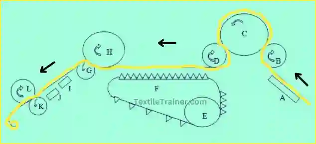
Main parts of Jute 1st Drawing Frame:
| A= Back plate | B= Back retaining roller |
| C= Jockey or slip roller | D= Front retaining roller. |
| E= Faller carrier sprocket. | F= Gill pin |
| G= Drawing roller | H= Drawing pressing roller |
| I=Guide plate | J= Doubling plate |
| K= Delivery roller | L=Delivery pressing roller |
Working Principle:
- Rolls of finisher card delivery sliver feed from the bottom fluted feed roller.
- A sliver is passed over the back plate “A” side by side, then under the back retaining roller “B”, then over the slip roller or jockey roller “C”, and then under the front retaining roller “D”.
- After passing over the moving gills “F”, the slivers are embedded in the pins of the gills.
- After drafting, the slivers pass between the drawing (front) roller “G” and the front pressing roller “H” to reach the guide plate “I”.
- In front of the guide plate, there is a doubling plate “J” that groups the slivers in equal numbers for doubling and then delivers them between the delivery roller “K” and the delivery pressing roller “L”.
- During draft, the fibers held by the gill pin bed become straight due to a higher speed of drawing and drawing pressing roller than the retaining rollers, reducing the weight per unit length of the sliver.
- As a result of doubling, the irregularity of the sliver greatly reduce.
Conclusion:
We learned a lot about jute 1st drawing frame through this experiment, which is very important for us. In this experiment, we learned the functions and parts of a jute first drawing frame. We also learned how the frame works. Thanks to our teacher, we were able to do this. It will help us in the future in the factory.
You May Read:
- Dynamic Layout Plan of Spinning Lab.
- Bale Breaker Material Passage Diagram: Easy Description.
- Step Cleaner Machine: Simple Working Principle.
- Hopper Feeder Machine in Blow Room with Simple Working Principle.
- Porcupine Opener Machine in Blow Room: Simple Working Principle.
- Scutcher Machine in Blow Room: Feed to Carding Effective Way.
- Material Passage Diagram of Carding Machine with Easy Description.
- Material Passage Diagram of Lap Former Machine.
- Working Principle of Comber Machine: Better Quality Yarn.
- Working Principle of Speed Frame in Ring Spinning with Simple Description.
- Ring Spinning Frame: Working Principle is Describe Very Easy Way.
- Easy Way: Autoconer in spinning working Principle.