Experiment Name:
Lab Report: Study on material passage diagram of jute 2nd drawing frame/ Study on working principle of jute second drawing frame.
Introduction:
After the carding process in the manufacturing of jute is complete, the jute is taken into the drawing frames, which are used to draw out the sliver to a smaller size, by using rollers, and straighten or comb the fiber, which will make it spin into a strong thread. A small sliver is discharged from a finisher card through a first drawing frame, which passes four slivers. In a jute second drawing frame, the sliver is further combed and drawn to produce roving, and then it is processed further into roving frames.
Objectives:
- To know about jute 2nd drawing frame.
- Come to learn function of jute second drawing frame.
- To know main parts of jute 2nd drawing frame.
- Come to learn working principle of jute second drawing frame.
General Specification of Jute 2nd Drawing Frame:
- No. of sliver feed/head = 6
- No. of head = 3
- No. of delivery/head = 2
- Faller pitch = 1/2
- Doubling ratio = 3: 1 (6:2)
- Draft range = 5-7.
Diagram of Jute 2nd Drawing Frame:
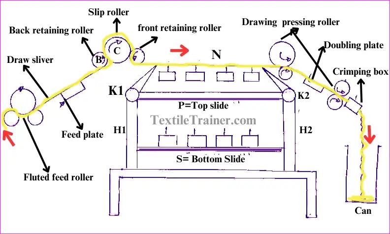
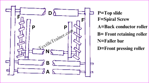
Working Principle of Jute 2nd Drawing Frame:
- Drawing frame with 3 heads, 6 slivers per head, and 2 deliveries per head. Here the doubling ratio is 3:1, i.e. 3 slivers are doubled into one.
- In this drawing frame, the faller bars (N) are propelled along spiral screws (F).
- There are two sets of top slides (p) on each head along which the faller bars (N) travel. These top slides are supported by two top spiral screws (F).
- For one revolution of the top screws, the two faller bars drop down. This is because the fallers have a travel equal to the lead of the screw or twice the pitch of the faller bars.
- In order for each faller to pass down the bottom slide (S) between the end of slide (P) and spring H1, the guide spring (H1) must be pushed away from slide (P) as they approach the forward end of the top slide. The downward peerage of the faller bar is assisted by a cam arrangement. Two bottom S support the fallers during their back journey.
- Here, however, the bottom screws have a courser pitch than the pot screws.
- A faller on the bottom screws reaches its backmost position when it presses the guide spring (H2) allowing it a passage for raising to the top screws (E). Cams aid in this lift.
- From the feed end, slivers pass over the conductor roller (A), the back retaining roller (B), the slip roller (C), and the front retaining roller (N) before reaching the gills. After required drafting, the slivers are passed between delivery pressing rollers then over.
Conclusion:
The experiment helped us to learn the names of different parts of the jute drawing frame. We also learned the working principle of the jute drawing frame. Thanks to our teacher for guiding us through the experiment.
You May Read:
- Jute First Drawing Frame: Easy Material Passage Diagram.
- Dynamic Layout Plan of Spinning Lab.
- Bale Breaker Material Passage Diagram: Easy Description.
- Step Cleaner Machine: Simple Working Principle.
- Hopper Feeder Machine in Blow Room with Simple Working Principle.
- Porcupine Opener Machine in Blow Room: Simple Working Principle.
- Scutcher Machine in Blow Room: Feed to Carding Effective Way.
- Material Passage Diagram of Carding Machine with Easy Description.
- Material Passage Diagram of Lap Former Machine.
- Working Principle of Comber Machine: Better Quality Yarn.
- Working Principle of Speed Frame in Ring Spinning with Simple Description.
- Ring Spinning Frame: Working Principle is Describe Very Easy Way.
- Easy Way: Autoconer in spinning working Principle.

I loved your blog article.