Experiment Name:
Lab Report: Study on material passage diagram of Speed frame or fly frame or roving frame or simplex in ring spinning.
Introduction:
A speed frame is placed after the finisher draw frame in a yarn manufacturing system. As the sliver produced by the finisher draw frame is thicker, it cannot be fed directly into the ring frame for yarn production. Therefore, the sliver is treated before entering the ring frame for yarn production. Fly frame or speed frame are commonly used simplex machines for cotton. A speed frame is a machine where the sliver is subjected to attenuating processes, and it receives a small amount of protective twist before being wound onto bobbins ready for creeling. The other name for speed frame machine :-
- Simplex frame
- Roving frame
- Fly frame
Objectives:
- To know about speed frame.
- Come to learn main function of these machine.
- Come to learn different parts name of speed frame.
- To know material passage diagram of these machine.
Main Operation of Speed Frame:
- Creeling : Through creeling, small amounts of draft are applied to the drawn sliver.
- Drafting: Drawn sliver is attenuated by drafting to produce the required amount of robin. Thick drawn sliver is converted into thin roving by drafting.
- Twisting: By twisting, a small amount of twist is inserted into the drafted fibre strand.
- Building: It is important to construct the roving on the bobbin in such a way as to facilitate its unwinding, handling, and transfer to the next process.
- Winding: The produced or twisted roving is wound on a bobbin and fed into the ring frame by the winding process.
- Doffing: This is an optional function of the speed frame. Doffing can be performed manually or automatically.
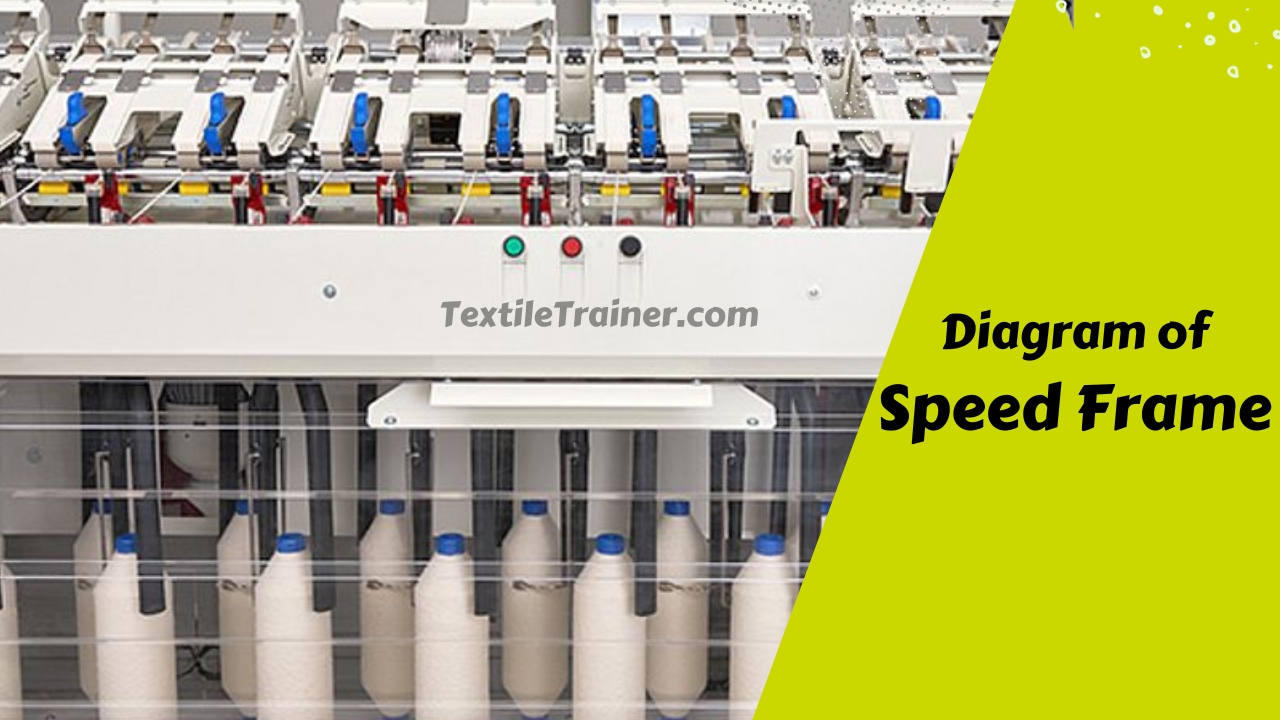
Diagram of Speed Frame:
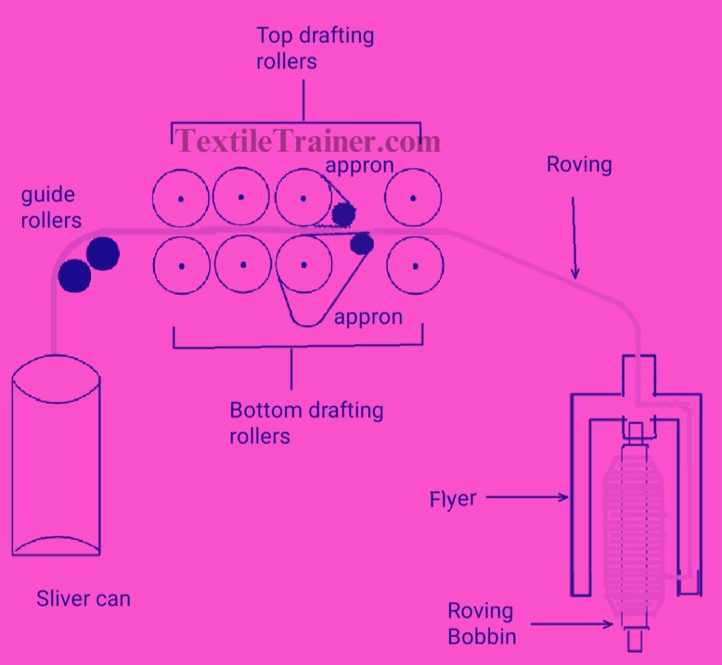
Main Parts of Speed Frame:
- Creel unit:
- Silver can
- Silver guide/ transport roller and
- Creel stand
- Trumpet/ condenser
- Optical sensor
- Drafting arrangement (4 over 4 drafting system)
- Top roller/(cot roller)
- Bottom roller(Fluted)
- Pressure arm
- Apron( Top & bottom)
- Spacer
- Cradle,
- Nose Bar
- Trumpet &
- Traverse Bar
- Cleaner cloth
- Sunction system
- Guide
- Flyer:
- Flyer Eye/Top
- Flyer Leg&
- Pressure arm
- Spindle
- Bobbin Rail
- Bobbin Holder &
- Dead Weight
Working Principle of Speed Frame:
- The first step is to feed the drawn sliver to the simplex machine using the creel and guide bar.
- A sliver went to a four over four drafting system, which means four top rollers are over four bottom rollers.
- In the front zone, there is a top apron and bottom apron which control the path of the floating fibers.
- An apron spacer or distance clip keeps the distance between the top and bottom apron proper.
- A drafted stand of fibres is then run through flyers. The flyers give the sliver the false twist, with one side attached to the front pair rollers and another to the bobbins.
- Lastly, the roving is wound and built on the bobbin.
- Then, doffing is done manually or automatically.
Conclusion:
The passes of material through the simplex machine are easy. Three works are performed on the sliver during this passage; drafting, twisting and winding. The result is roving, which is then fed into the ring frame. A ring frame is the last machine in yarn spinning and after it, yarn is produced.
You May Read:
- Dynamic Layout Plan of Spinning Lab.
- Bale Breaker Material Passage Diagram: Easy Description.
- Step Cleaner Machine: Simple Working Principle.
- Hopper Feeder Machine in Blow Room with Simple Working Principle.
- Porcupine Opener Machine in Blow Room: Simple Working Principle.
- Scutcher Machine in Blow Room: Feed to Carding Effective Way.
- Material Passage Diagram of Carding Machine with Easy Description.
- Material Passage Diagram of Lap Former Machine.
- Working Principle of Comber Machine: Better Quality Yarn.

Great, thanks for sharing this blog post.Much thanks again. Keep writing.