Yarn Path Diagram of Power loom with Basic parts
Experiment Name:
Lab Report: Study on Yarn path diagram of power loom./Study on Yarn path diagram and the basic parts of power loom.
Introduction:
Weaving fabric is made using a loom, a machine that has different parts. Each part has a distinct function. One of the key developments during the early Industrial Revolution was the introduction of the power loom, a mechanized loom powered by a line shaft.
Objectives:
- To know about power loom.
- To know about yarn path of power loom.
- To know about important parts of power loom.
Diagram of Power Loom:
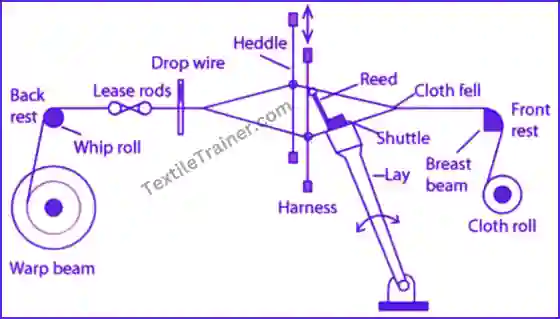
Main Parts of Power Loom:
- Warp Beam: During warping, the warp beam, which holds warp yarns, is controlled so that it releases warp yarns to the weaving area of the loom as needed.
- Heald: Known also as a heddle, it holds the warp yarns in place, helps to form sheds, and is used to determine fabric warp thread density.
- Heald shaft: There are several heald wires on the heald shaft that carry the ends of the warp sheet and are related to the shedding mechanism. They are usually made of wood or metal such as aluminium. Heald shafts are also known as heald frames or staves. The number of heald shafts is determined by the number of warp repeats in the weave. A weave’s drafting plan determines the number of heald shafts needed. The main function of the heald shaft is given below:
- It helps to form sheds.
- Identifying broken warp threads is made easier with this tool.
- Maintains the sequence of the warp threads.
- It determines how many heels should be raised or lowered in order to form the design or pattern on a fabric.
- The number of heald wires per inch determines the warp thread density in a fabric.
- Shuttle: The shuttle is a weft carrier that helps weave the weft threads into the warp threads to form cloth. shuttle is made of wood. It passes from one end of the loom to another. After passing through the warp shed, the shuttle enters a shuttle box fitted at either end of the loom. It travels along the wooden sley race between the top and bottom layers of the warp sheet. A shuttle weighs approximately 0.45 kilograms.
- Shuttle box: The box is made of wood and houses the shuttle. It has a spindle and picker. It may also accommodate the picker without spindle. The top and sides of the box towards the sley race are open. During the intermediate period between two picks, the shuttle resides inside the box.
- Picker: Pickers are made of leather or synthetic materials. They are placed on a spindle or grooves in shuttle boxes to drive the shuttle from one to another. They also sustain the shuttle’s force while entering the box.
- Beams: In this cylinder, the multiple warp ends are used so that yarns can be removed as warp sheets.
- Breast Beam: Often called the front rest, it is placed above the cloth roller at the front of the loom and acts as a guide as the cloth is wound onto it. As well as maintaining proper tension for weaving, the front and back rests maintain the warp yarns and cloth in horizontal position.
- Back Beam: Back beam also known as the back rest. It is placed above the weaver’s beam. It may be fixed or floating. In the first case, it merely acts as a guide for the warp sheet coming from the weaver’s beam. Second, it serves both as a guide as well as a tension sensor.
- Lease rods: A lease is the division of warp yarns into one and one, two and two, etc. Two rods pass between these two divisions. These are called lease rods.
- Slay: Slay is made of wood. It also consists of the sley race or race board, reed cap and metal swords carried at either end. The sley mechanism swings to and fro. By using a beat up motion, the sley pushes the last picks of weft to the cloth’s fall. In an unequal movement, the sley moves faster in the direction of the cloth and slower in the direction of the backwards motion. This movement is known as eccentricity of the sley. Beat up is performed with the help of a metal reed attached to the sley in order to provide sufficient time for shuttles to pass through the warp shed.
- Reed: Reed is a metallic comb that is fixed to the sley with a reed cap. There are many wires in the reed, which are separated by holes, which are known as dent holes. Each hole can accommodate one, two or more warp ends. The number of dents in two inches determines the number of reeds. Following is a list of some of the functions performed by the reed:
- It pushes the last pick of weft to the bottom of the cloth
- Assists in maintaining the warp thread position
- It guides the shuttle as it passes from one end of the loom to the other.
- Combined with healds, it determines the fineness of the cloth.
- The fabric’s openness or closeness is determined by it.
- Treadle: A treadle is a paddle or lever placed under a loom. Cords connect the thread to the treadle.
- Temple: A part that supports the width of the cloth at the edges.
- Cloth Beam: Known also as the cloth roller, it is wound with woven cloth and placed below the front rest. It is also known as the cloth roller. It is wound with woven cloth and placed below the front rest.
- Picking Stick or Arm: On a picker, it is an arm or stick made of wood that gives motion.
Conclusion:
We learned about power looms, as well as the names and functions of the different parts of a power loom. Thanks to our teacher for helping us. We will use this knowledge later in our lives.
You May Read:
- Effective Layout Plan of Fabric Engineering Lab.
- Basic Principle of Weaving: Very Easy Way.
- Yarn Passage Diagram of Pirn Winding Machine is Described Easy Way.
- Yarn Passage Diagram of Circular Knitting Machine.
- Dynamic Layout Plan of Spinning Lab.
- Bale Breaker Material Passage Diagram: Easy Description.
- Step Cleaner Machine: Simple Working Principle.
- Hopper Feeder Machine in Blow Room with Simple Working Principle.
- Porcupine Opener Machine in Blow Room: Simple Working Principle.
- Scutcher Machine in Blow Room: Feed to Carding Effective Way.
- Material Passage Diagram of Carding Machine with Easy Description.
- Material Passage Diagram of Lap Former Machine.
- Working Principle of Comber Machine: Better Quality Yarn.
- Working Principle of Speed Frame in Ring Spinning with Simple Description.
- Ring Spinning Frame: Working Principle is Describe Very Easy Way.