What is Coiling Mechanism?
In order to store and transport the sliver, it must be coiled in a can. The storage of the sliver takes place in a specific way that is known as the coiling mechanism. Using the process of cycloidal deposition (Cycloidal deposition), a sliver can is uniformly deposited in an orderly fashion as the deliver is deposited. In the event that a sliver is drawn without coil formation, it will create definite problems as it is withdrawn from can in the draw frame. To reduce this issue, coiling mechanisms were introduced.
Object of Coiling Mechanism:
- The function of coiler mechanism is to lay the condensed sliver delivered by the calendar rollers in an orderly manner (Cycloidal deposition) in a cylindrical can.
- During the next process, a sliver from the can can be pulled out without becoming entangled or stretched.
Types of Coiling:
There are two types of coiling. They are mentioned below:
- Under center coiling.
- Over center coiling.
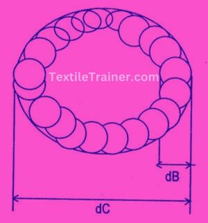
1. Under Center Coiling:
There is a coiling process known as under center coiling that is used when the diameter of the circle of the sliver is less than the diameter of the can’s radius. Under center coiling is widely used for cans of larger diameters. In the diameter relation, it should be as follows: dc/db = 2.5 (approx.)
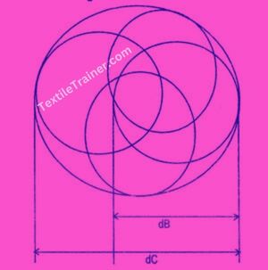
2. Over Center Coiling:
There is a coiling technique called over center coiling which is simply where the diameter of the sliver i.e., the diameter of the coils is greater than the diameter of the can itself. Over center coiling is generally used for small to medium sized cans up to 24″ in diameter. In the diameter relation, it should be as follows: dc/db = 1.45 (approx.)
Description of Coiling Mechanism:
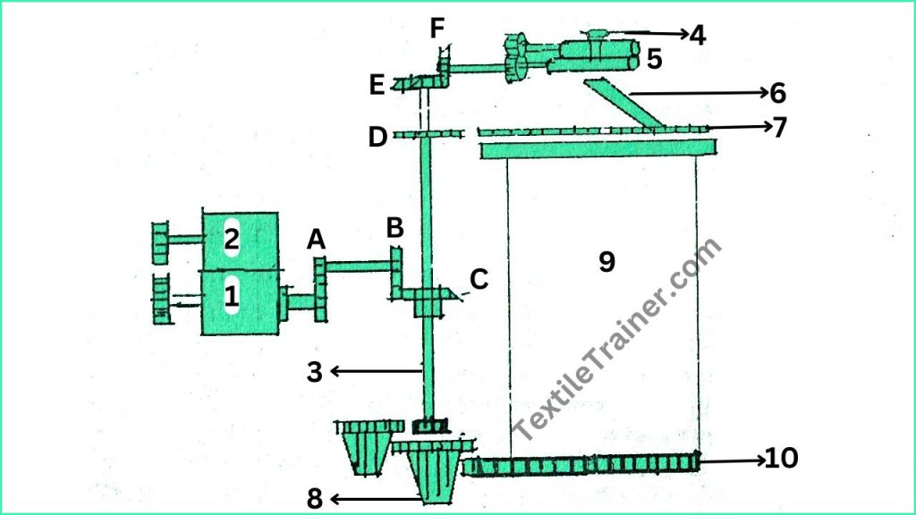
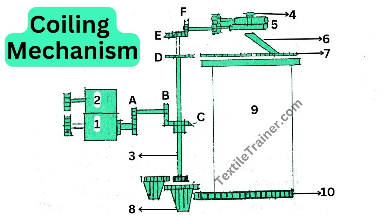
It is shown in the figure how the coiler is driven. The coiler gets its drive from the bottom calendar roller shaft through a gear (A), which drives the vertical shaft through a bevel gear (B) and (C). There are two bevel gears (E) and (F) that are attached to the vertical shaft at the top which drive the coiler calendar roller. The two coiler calendar rollers are being pressed together to form a nip below the coiler trumpet. The coiler calendar rollers are driven at a surface speed slightly higher than that of the calendar rollers to ensure there is tension in the sliver. A tube (7) is driven by gear (D) to ensure the tension in the sliver. It has an inclined tube (6) on the vertical shaft, with its upper end placed beneath the coiler calendar roller, allowing for the collection of sliver from the coiler calendar roller’s nip. As it is possible, the lower end of the coiler tube is provided with an exit point for the sliver at a point near its periphery, so that the sliver led coils into the can in a circular fashion. The can is positioned on a plate mounted on a reduction gearing driven from the bottom of the vertical shaft at a slow speed. The axis of the can is offset from that of the tube wheel.
You May Read:
- Objectives and basic function of carding machine.
- Working principle of carding machine.
- Why carding is called heart of spinning?
- Operating zone of carding machine.
- Neps in carding machine.
- Function of carding machine.
- Types of card clothing with advantage and disadvantage.
- Flexible card clothing vs metallic card clothing.
- Action of carding machine.
- Stripping in carding.
Reference:
- Belal, P. D. (2016). Understanding Textiles for a Merchandiser. Dhaka: LB Graphics & Printing.
- Chowdhury, M. F. (2016). Manual of short staple spinning. Dhaka: Granthanir Prokashoni.
- Kadolph, S. J. (2006). Textiles. New Delhi: Pearson Education.
- Prof. Dr. Engr. Ayub Nabi Khan, E. M. (2088). Principles of short staple spinning. Dhaka: Books Fair.



very informative articles or reviews at this time.
Wow, you’re great. No, I don’t think I’ve ever seen anything like it before in print.